Installations inside the mound
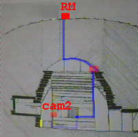
 Position and view angle of camera's
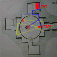
 View from above
View to right recess
View from above
View to right recess
The picture provide an insight what installations is necessary inside
Maeshowe. The following info can be gotten from the picture:
The following cables are needed inside the mound (color of cables preferable
dark; e.g. brown, black):
-
Howard video camera:
-
twin lead power cable (low voltage)
12 m, male (6.1mm O.D., 2.1 mm I.D.), female (5.0 mm O.D., 2.1 mm I.D.)
-
coax RG58 cable (video)
12 m, male RCA, male RCA
-
shielded cable (audio mono)
12 m, male 3.5 mm jack mono, male RCA
-
Radio modems
-
twin lead power cable (low voltage)
15 m, male 2.5 mm DC power jack, female 2.5 mm DC power jack
-
RS232 hardware flow control (towards PC)
15 m, DB9 male, DB25 female (this
should be able to transport 57.6 kbit/s)
-
RS232 hardware flow control (towards telephone modem)
15 m. DB9 male, DB25 female (this
should be able to transport 57.6 kbit/s)
-
RS232 cross cable, hardware flow control (telephone modem)
2 m, DB25 male, DB25 male
-
RS232 hardware flow control (towards PC)
2 m. DB9 female, DB25 female
(this should be able to transport 57.6 kbit/s)
-
Videorecorder
-
SCART cable
2 m, Video in, female RCA, RG58
2 m, Video in, male RCA, RG58 (so a direct connection from to the other
'Video in')
2 m, Video out, male RCA. RG58
2 m, Audio in L, female 3.5 mm jack mono. shielded
2 m, Audio in L, female 3.5 mm jack mono. shielded (so a direct connection
to the other 'Audio in L')
2 m, Audio out L, female 3.5 mm jack mono. shielded
-
Power
-
220V power block (mound)
8 Eurotype connectors, include earthing
5 m cable
-
220V power block (Tormiston Mill)
3 Eurotype connectors, include earthing
5 m cable
Pin layout
Radio modem connector (all DB9 male/female)
1 may not be connected
2 RD
3 TD
4 DTR
5 Ground
6 DSR
7 RTS
8 CTS
9 may not be connected
Other RS232 connectors (all DB25 male/female)
1
13 1
5
_______________________________
_______________
\ . . . . . . . . . . . .
. / \ . . . . . /
\ . . . . . . . . .
. . . / \ . . . .
/
---------------------------
-----------
14
25 6
9
Name (V24) 25pin 9pin Dir Full name
Remarks
--------------------------------------------------------------------------
TxD
2 3 o Transmit Data
RxD
3 2 i Receive Data
RTS
4 7 o Request To
Send
CTS
5 8 i Clear To Send
DTR
20 4 o Data Terminal
Ready
DSR
6 6 i Data Set Ready
RI
22 9 i Ring Indicator
DCD
8 1 i Data Carrier
Detect
GND
7 5 - Signal ground
-
1 - - Protective
ground Don't use this one
for signal ground!
Disclaimer and Copyright
Last content related changes: November 6, 1997