Simple wokflow to determine a windmill's biotope
Simple workflow to determine a windmill's
biotope by Victor Reijs
is licensed under CC BY-NC-SA 4.0


Introduction
I started in 2020 (during COVID times) to look at using CFD programs
for evaluting the biotope around traditional windmills. This
resulted in the following ideas that can be of use when looking at
this:
I use on this web page De Zwiepse Molen as example. There is also
a workflow for the Impington Mill.
Making a CAD-model
The program to be used for making a CAD-model will need to be
able to export the CAD-model in a recognisable format for the
CFD-program.
One could try a windtunnel, but that would not be easy to
accomodate to the wind mill nevironment. It though looks that
CFD's results are comparbale to windtunnel results (to relatively
low speeds: say between 2 and 7BFT); see for instance here and here.
I am using the CFD cloud service SIMSCALE which can import STF files,
and such files can be provided by SketchUp CAD-program.
Both SketchUp and SIMSCALE are profession programs/services.
Pro[fessional] versions cost also considerable amounts of money
(several hunderds of Euros).
Anyway we are making a CAD model with SketchUp. SketchUp Free version
is well equiped for the windmill environment. In this program one
can easily make 3D forms, such as: boxes, roofed boxes, cylinders,
capped cones, trees, etc, etc.
Houses that are around a windmill, can be simulated by a box
(with its height: the wall height plus half the roof height); or
otherwise a more precise model (box with hipped roof, etc.). A
windmill can be a simple standing cylinder. Don't go into too much
details as that will not have much influence on the CFD results.
Furthermore, buildings below the ground/bailey height are
certainly not in need of precise dimensions.
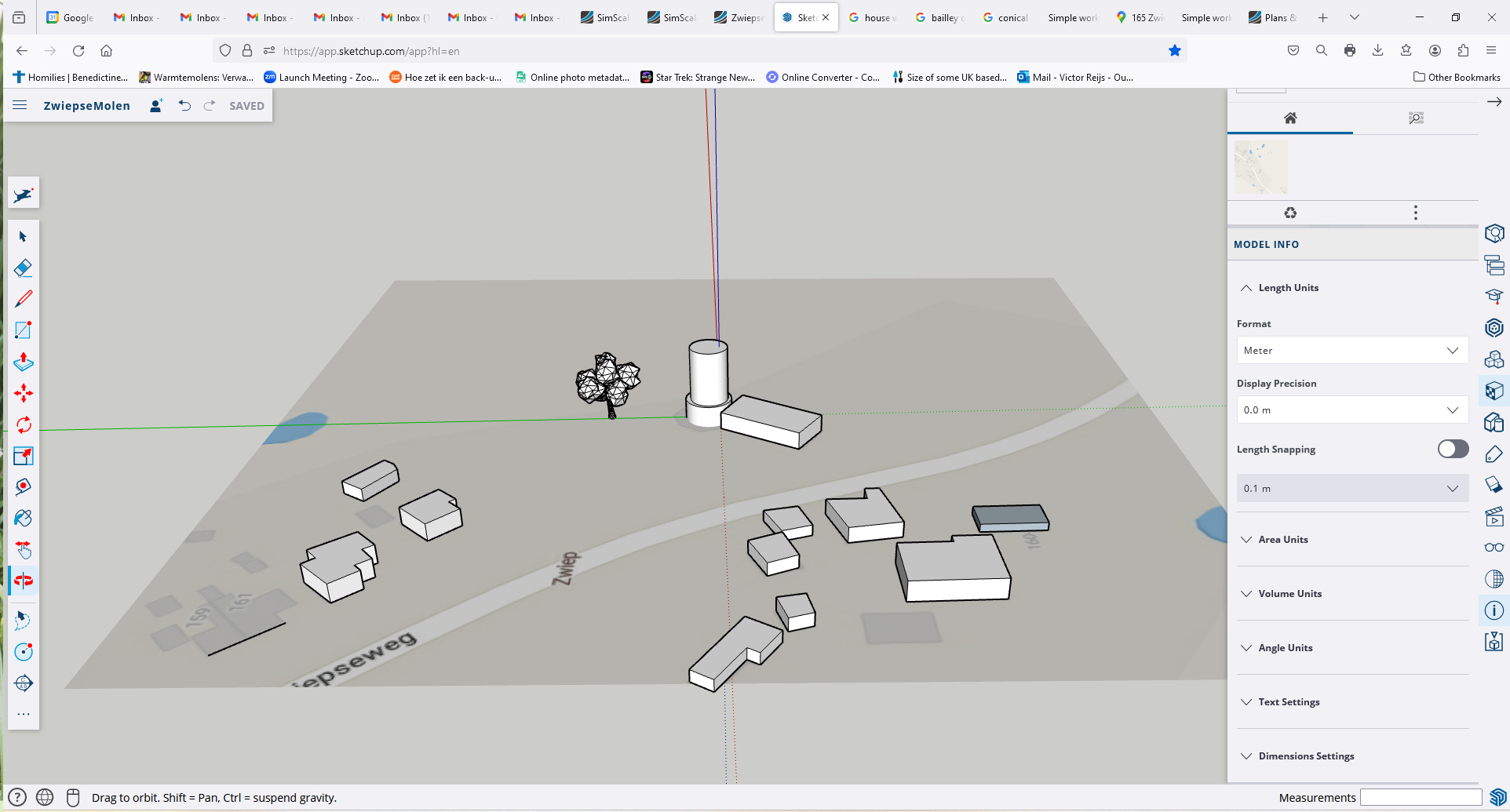
The folowing steps for making the CAD-model can be seen as a
guide line (Zwiepse Molen has
been taken as an example):
- Define in
SketchUp the unit of the dimensions (CFD uses m[etres], so
do the same in SketchUp): Model Info (i) → Length
Units → Meter; Model Info (i) →
Display precissio → 0.00 m; and Model Info (i)
→ Length Snapping → OFF
- One can add a piece map from of Google Map (so when get an
idea where buildings are), use: ≡ → Add Location →
Select Region → Import
- Having imported this, one can now trace the contours of the
building-plans (Line-tool). Make sure you have zoomed in enough
as that is easier to trace. Make also sure that your buildings
all go down to a height of 0m. One can also disable Lineair
inferences (OFF by using the Alt-button).
There is no real need to be very accurate (say within 0.25m).
- For the heights of the objects one can use in The Netherlands:
AHN (Actueel Hoogtebestand Nederland).
It also provides the map references in RD (RijksDriehoeksmeting).
For UK there is the Defra Data Service (which uses British National Grid
and see also OS Maps).
- After tracing the contours of the building plans, one can
increase their height by extruding them (Push-Pull tool). At the
right bottom of the window (Measurements) one can see the
pull height.
- For simplicity one simple use a box for a roofed
building: with its height: height of walls + half of height of
roof.
There is no real need to be very accurate (say within 0.25m).
Remark: Some other people
recommend to use the ridge height of the roof. Need to
investigate what is better.
- The mill is made by using a cicle (Circle-tool), pull up (Pull
tool) to form a cylinder: height of top is 18m, and windshaft
height is around 16m.
- Perhaps a mill should be simulated with a capped cone, but it
is easier for the velocity/energy analysis if a cylinder is used
(and that will also not provide signifant velocity differences).
- If a Google Map was used; make sure you push (Push-Pull tool)
the undersides of the buildings slightly below a 0m.
Remark: Make sure an object does not end very close to 0m;
otherwise 'mesh' problems can happen during the simulation.
- A leafed
tree (height 15.5m and distance from centre of mill 22m)
was included by importing it (blobbed object) from here:
≡ → Import → Device → Gotten tree.skp
This tree is at a nearer location where early 2023 a
smaller tree stood. So this is not the present/past situation.
The blobbed object was copied from this site.
- In the CAD-model only a single tree has been incorporated. In
the case of Zwiepse Molen many (unwanted) rows of trees are
windbreakers, so one should include such.
Remark: Can a row of trees be
simplified for a simulation? If you have ideas; let me know
- Make sure that no 3D object is touching/overlaying another
object. That migth cause problems in the simulation.
- Give the CAD-model a name and save.
Make sure that you check and recheck things as good as
possible, before downloading if for importing it into the CFD
program.
- And when the CAD-molen looks good, download it as STL:
≡ → Download → STL
Here is an example ZwiepseMolen.skp (made
in some 30 minutes):
Importing and editing the CAD-model in a
CFD-program
So we are making use of SIMSCALE. Make sure
you make a Community Plan
account. This Community Plan allows only for 10 simulations, so make
sure you have a good CAD-model and that you train/educate yourself around SIMSCALE.
The following steps can be done:
- Import the STL
model
- Edit this model by: Edit in CAD mode
- Delete the terrain (a Sheet in SIMSCALE)
- Make a External Flow Volume en delete all the
solids
- Save Copy
- Goto SIMULATIONS +
Run simulations in the CFD-program
The following steps can be done:
- Important: In the Community Plan of
SIMSCALE one only has a budget for 10 simulation; so make
sure you train/educate yourself
beforehand!!!
- Goto SIMULATIONS +
- Incompressible → Create Simulation
- Materials → Air → Apply
- Defined the Boundary conditions: Velocity inlet
(using ABL profile:
a West wind v=6.44m/sec @10m
[4.61 Bft]; z0=0.5m [6.4Bft])
(West side), Pressure outlet (East
side), Non-slip Wall (for the ground),
Slip Wall (for the remaining sides).
- Run the simulation (Simulation Runs +)
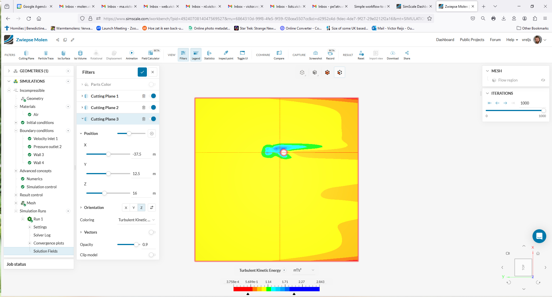
- When simulation ended (took some 25min), view the results (Solution
Fields).
- As much as possible default SIMSCALE options have been used
(like k-omega SST and residuals < 0.01).
Here is a SIMSCALE screengrab when the simulation has finished (KTE output at windshaft
height):
The results of simulation
The following can be see:
- Goto SIMULATIONS → Simulations Runs →
Run 1 →
Solution Fields
(a West wind blows from left (West) to right (East) at 6.44m/sec
@ 10m [4.61Bft])
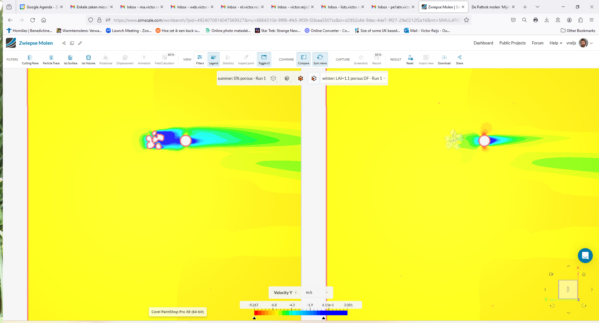
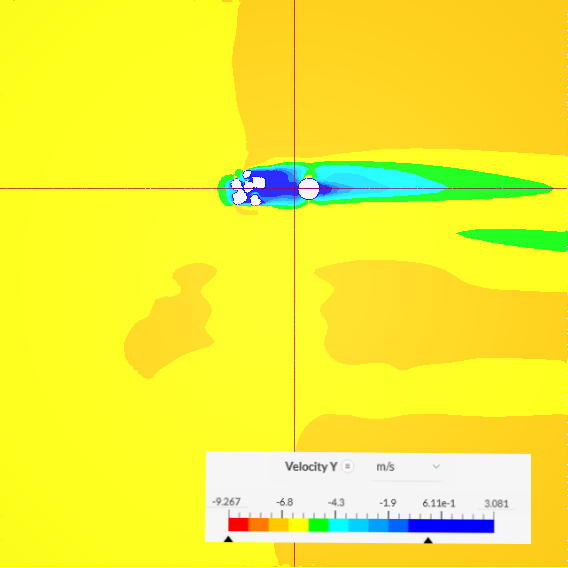
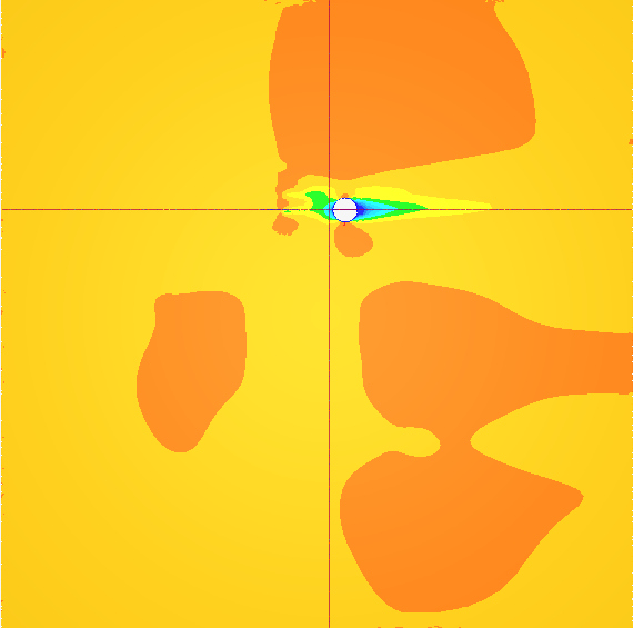
- Velocity Y (summer): Looking from above (there is a thin
horizontal line through centre tree and mill body; and a thin
vertical line at at plane of the sails):
3m height
|
Mid-tree (10m) height
|
windshaft (16m) height
|
 |
 |
 |
- All the buildings in this example (between 1.8 and 4.5m
high) were lower then the bailey (4.9m) of the windmill, so no
real influence on the wind pattern at mid-tree of windshaft
height.
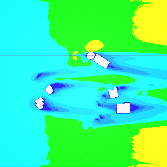
- Velocity Y (summer): Looking towards the North; through centre
the tree and windmill (there is a thin horizontal line at the
mid-tree height; and a thin vertical line at at plane of the
sails):
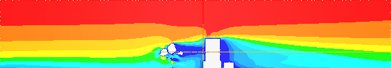
- One can recognise the cavity areas
(dark blue) behind the tree and the mill body.
- This cavity (turbulence) will catch the lower part of the
plane of the sails (so it will increase stress on the sail
beams).
- Velocity Y (summer): Looking towards the West; at plane of the
sails (there is a thin horizontal line at the windshaft height;
and a thin vertical line at at plane of the sails):
- One can recognise that the cavity (horizontal dark blue
patch) of the tree extend into the plane of the sails. Beside
this cavity area due to the tree; the upwind
recirculation area (vertical dark blue patch) due to the
mill body (in front of the mill) can be seen.
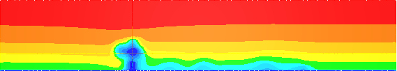
- Turbulent Kinetic Energy (KTE) (summer):
Looking towards the North; through centre the tree and windmill
(there is a thin horizontal line at the windshaft height; and a
thin vertical line at at plane of the sails). Here is
the combination of the ABL's inherent turbulence and the
objects' extra turbulence:
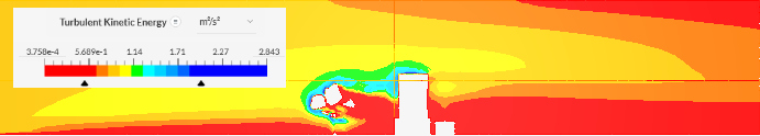
- One can recognise the turbulence in the cavity
boundary area (green/blueish area) behind the tree and
less cavity turbulence behind the mill body.
- This turbulence will catch the middle part of the plane of
the sails (so it will increase stress on the sail beams).
- Remark: Would be nice if
SIMSCALE includes Turbulence
Intensity as output, so it can report on a
normalised turbulence.
- An analysis of how to model a leafed or leafless deciduous
tree can be seen
here. If one looks at leafed tree the earlier used blobbed tree model
is ok. If one wants to use Darcy-Forchheimer coefficients for
porosity the below points can help:
- This simulation in SIMSCALE Community Plan gives an idea of
the influences of obstacles and works well for tradtional
windmill biotope.
Evaluating the results
A full example (using a different windmill) of
evaluating the simuation results can be seen here
(link might not be available, let me know).
Conclusions
Both SketchUp Free and SIMSCALE Community Plan can
be used within the traditional windmill biotope environment.
Referenties
SIMSCALE (accessed Feb. 8, 2024)
SketchUp (accessed Feb. 8, 2024)
Acknowledgements
I would like to thank people, such as SIMSCALE
support team, and others for their help, encouragement
and/or constructive feedback. Any remaining errors in
methodology or results are my responsibility of course!!! If you
want to provide constructive feedback, please let me know.
Major content related
changes: February 8, 2024