NEW


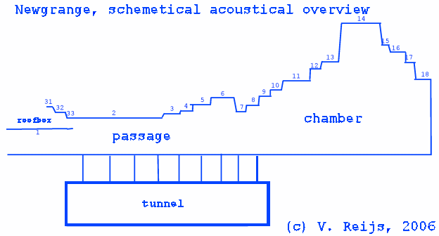
| Segment |
Start
of segment seen from end seg7 [m] |
End
of segment seen from end seg7 [m] |
Area
start [m2] |
Area
end [m2] |
Cumulative
volume from end seg18 [m3] |
| Passage |
|||||
| 1 |
13.78 |
10.2 |
1.4 |
1.4 |
- |
| 2 |
10.2 |
5.8 |
1.5 |
1.5 |
99.0 |
| 2A |
5.8 |
5.7 |
1.5 |
1.4 |
92.3 |
| 3 |
5.7 |
3.85 |
1.4 |
1.4 |
92.1 |
| 3A |
3.85 |
3.75 |
1.4 |
1.5 |
89.5 |
| 4 |
3.75 |
3.16 |
1.5 |
1.5 |
89.4 |
| 4A |
3.16 |
3.06 |
1.5 |
1.7 |
88.5 |
| 5 |
3.06 |
1.94 |
1.7 |
1.7 |
88.3 |
| 5A |
1.94 |
1.84 |
1.7 |
2.0 |
86.4 |
| 6 |
1.84 |
0.58 |
2.0 |
2.0 |
86.2 |
| 6A |
0.58 |
0.48 |
2.0 |
1.2 |
83.7 |
| 7 |
0.48 |
0 |
1.2 |
1.2 |
83.5 |
| Chamber (possible start) | |||||
| 7A |
0 |
-0.10 |
1.2 |
1.4 |
83.0 |
| 8 |
-0.10 |
-0.77 |
1.4 |
1.4 |
82.8 |
| 8A |
-0.77 |
-0.87 |
1.4 |
1.8 |
81.9 |
| 9 |
-0.87 |
-1.42 |
1.8 |
1.8 |
81.7 |
| 9A |
-1.42 |
-1.52 |
1.8 |
2.1 |
80.7 |
| 10 |
-1.52 |
-1.99 |
2.1 |
2.1 |
80.5 |
| 10A |
-1.99 |
-2.09 |
2.1 |
2.4 |
79.5 |
| 11 |
-2.09 |
-3.66 |
2.4 |
2.4 |
79.3 |
| 11A |
-3.66 |
-3.76 |
2.4 |
2.9 |
75.4 |
| 12 |
-3.76 |
-4.26 |
2.9 |
2.9 |
75.2 |
| 12A |
-4.26 |
-4.36 |
2.9 |
3.2 |
73.7 |
| 13 |
-4.36 |
-5.36 |
3.2 |
3.2 |
73.4 |
| 14 |
-5.36 |
-7.81 |
21.3 |
21.3 |
70.2 |
| 15 |
-7.81 |
-8.26 |
8.3 |
8.3 |
18.0 |
| 16 |
-8.26 |
-8.97 |
6.4 |
6.4 |
14.3 |
| 17 |
-8.97 |
-9.63 |
7.4 |
7.4 |
9.7 |
| 18 |
-9.63 |
-10.56 |
5.2 |
5.2 |
4.8 |
| Roofbox |
|||||
| 31 |
11.38 |
11.12 |
0.78 |
0.78 |
- |
| 31A |
11.12 |
11.02 |
0.78 |
0.55 |
- |
| 32 |
11.02 |
10.46 |
0.55 |
0.55 |
- |
| 32A |
10.46 |
10.36 |
0.55 |
0.27 |
- |
| 33 |
10.36 |
10.2 |
0.27 |
0.27 |
- |
| Tunnel |
|||||
| Tunnel |
11.1 |
- |
- |
- |
49.2 |

