 Home
Home Up
Up Search
 Mail
Mail
NEW
Evaluating the lunar observations on July 31st 2023
at Calanais I
Introduction
On tis web page, the ground proofing of the 3D scenery of
Calanais I site
within Stellarium will be done at only three levels:
- Determining the azimuth (rotation of vertical axis) of the 3D
laser scan
- Determining the tilt (rotation of East-West axis) 3D laser
scan to give the apparent altitude
- Determining if the whole 3D laser scan has to be vertically
and East-West transformed with respect to Cnoc and Turso's DSM.
These three levels are hopefully enough to get a good South
viewing skyline (from the end of the avenue: near stone 8 and 19).
More rotations/transformations could be needed, but that cannot be
determined with the present camera location.
Steps to ground proof the
Calanais I
3D scenery
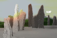
On July 31st 2023 some 23 photos were taken (by
E. Rennie) to record the Moon going over/through the
Calanais I
site. These photos are being used to ground proof the Calanais I 3D scenery in
Stellarium using the three mentioned levels.
The following steps have been used for the preparation
- Camera
- FUJIFILM; Digital Camera X-T3
- Geotagging (aka GPS Date/Time) works only through
the Fuji App, which is on the smartphone. The timing is though
all over the place, so it can't be used.
- The EXIF data (Create Date and Shutter Speed)
of the photos has been used to calculated: a photo's Average
time (= [EXIF Create Date] + Offset + [EXIF Shutter Speed]/2).
- Times are in EXIF not defined properly (is it before the
shutter is opened or after: see Section Time Tags). As the Shutter
speed was relative long (in many cases around 20sec)
it is important to know the definition of the EXIF Create
Date. It
has been verified that for a FUJIFILM E510 and FUJIFILM
X-T3 the EXIF Create Date is the moment the
camera button is pressed.
So the average time is half the Shutter
speed after the EXIF Create Date
(assuming the photo has been averaged over the whole
exposure).
- Photo taking workflow
- The clock on the camera is checked (to determining the Offset) just before the photo
session with a Windows 10 system (which had just been
synced using NTP). The Offset is found by
taking a photo of the Windows time/clock screen (including
seconds!).
- Place camera on tripod as near as possible near stone 8 and
facing towards the circle. Zoom, so that the whole site is in
the photo (around 50deg FOV). Keep zoom and position of camera
during the whole session the same.
- Take photos at discrete positions of the Moon: left, middle
or right of a certain stone contour (also left, middle or
right).
- The clock on the camera is checked (checking again the Offset)
just after the photo session with a Windows 10 system (which had just been
synced using NTP). The check is done by taking a photo
of the Windows time/clock screen (including seconds!).
- Timing
- For each photo, with its Average time, the Moon's
azimuth is calculated: azimuthEXIF.
- Tools
- The 3D scenery of
Calanais I
(version: callanish1_Readjusted_20230505, including
Cnoc an Turso) in Stellarium
(version 23.2) has been used.
- ARCHAEOCOSMO
(with Swiss Ephemeris and Excel) has been used to calculate
the Moon's apparent position (azimuth).
- PSP (Coral Paint Shop Pro X9) was used to layer Stellarium
screen grabs on the photos
- Animated gif files were used to
show the matching of a photo with Stellarium screenshot.
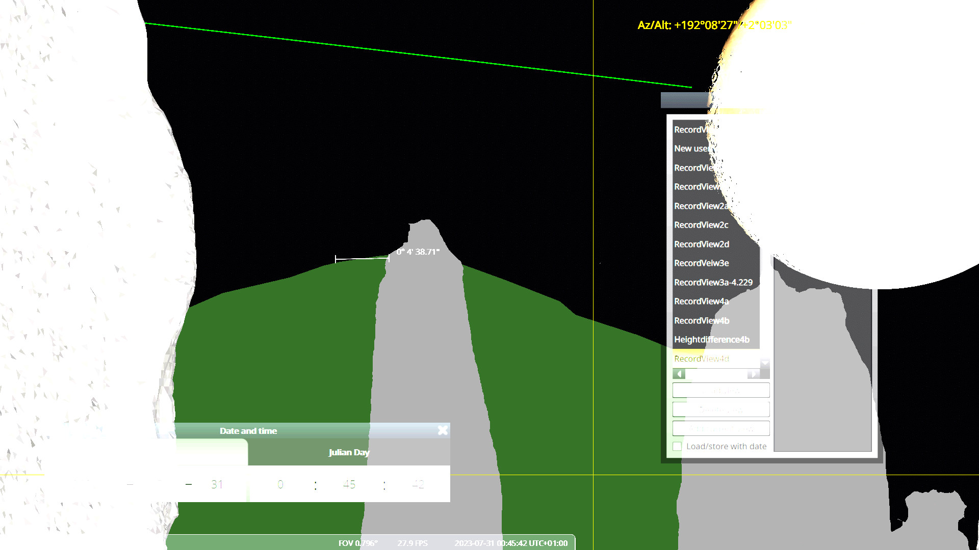
Aligning the azimuth
- The camera location (part of View in
Stellarium) needs to be found in the 3D scenery. This can be
determined iteratively by mapping the stones in a photo over the
stones in the 3D scenery (using PSP).
- Method 1: Discrete Moon positions (the taking of photos was
also planned at such positions)
- Stellarium was used to determine the azimuths of the 3D
scenery's discrete stone-features in relation to the discrete
position of the Moon (left edge, right edge, or middle): azimuthDis
- The azimuthDis and azimuthEXIF
were compared (azimuthEXIF -
azimuthDis), producing difference RotVertDis.
- Method 2: Continuous Moon positions
- In Stellarium the time was determined when the Moon was at a
similar position as in the photo. The Average time was
used to determine the Moon's apparent position: azimuthCon.
- The azimuthCon and azimuthEXIF
were compared (azimuthEXIF - azimuthCon),
producing difference RotVertCon.
- Method 1 is expected to be less accurate as it uses only
discrete Moon and stone positions, Method 2 really looks at the
real positions od Moon and stones in the photo. But the two
methods should provide similar averages; the standard deviation
(1σ) of Method 1 might be somewhat larger (due to the courser
discrete Moon and stone position) than of Method 2.
- Method 2 is the preferred method.
- The standard deviation (1σ) provides an idea of the accuracy
one can reach using photos and EXIF data.
- If the median difference (RotVertCon)
is zero, the 3D scenery is correctly aligned in Stellarium.
If not, one needs to rotate the 3D scenery in the vertical axis
with the median difference: using convergence_angle ~
from_grid - RotVertCon in scenery3d.ini.
This needs to be iteratively repeated (start again at the first bulletin in this
section) until the 3D scenery is properly aligned in
azimuth.
Aligning the apparent altitude
When the azimuth of the 3D scenery is aligned, the apparent
altitude of the 3D scenery needs to be aligned:
- First one needs to make sure that the height of the camera
location (part of View in Stellarium) is correct.
- This can be checked best where nearby stones (e.g. stone 7, 6,
5 and 4) and far away stones are overlapping (e.g. stone 30)
- When the height of the camera (in View of Stellarium)
is correct, we use a photo where a specific part of the Moon
(e.g. bottom rim) just touches a top of (far away) stone (e.g.
stone 27). This gives RotEW.
- If the Moon does not touch that stone properly in 3D scenery
(e.g. DSCF8622), one will need to rotate the 3D scenery in the
East-West axis with RotEW.
Positioning the whole 3D laser scan
In the photos the Cnoc an Turso's skyline can be seen and this
must be aligned with the Cnoc an Turso's skyline constructed by
its DSM. In Stellarium one can determine the angle difference: Cnoc-XXXangle.
This can be transformed into a vertical transformation using:
Transvert = DistanceCnoc
* tan(Cnoc-Vertangle)
with DistanceCnoc around 175m.
This can be transformed into a East-West
transformation using:
TransEW = DistanceCnoc
* tan(Cnoc-EWangle)
Transforms in East and North direction are positive numbers.
Remember this displace is due to general height error of the 3D
laser scan and the resolution of the Cnoc an Turso 25cm DSM.
First iteration
This first iteration (based on callanish1_Readjusted_20230505)
will derived the results for azimuth, apparent altitude and height
of whole 3D laser scan. Hopefully this first iteration gives for
all three adjustment a value of (close to) zero.
Azimuth
The distribution of RotVertCon and RotVertDis
are derived for different convergence_angles.
convergence_angle=from_grid (-4.03255°)
We started the analysis with the default convergence angle
(from_grid) and this gave the following results:
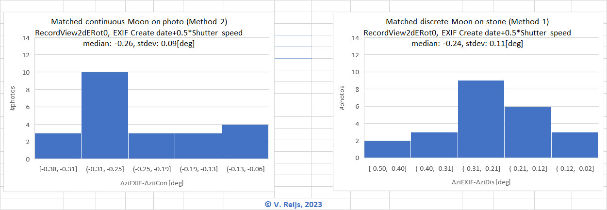
This gives an median RotVertCon of around
-0.26deg (with a standard deviation of 0.09deg) for Method 2. As
expected, the standard deviation for Method 1 is a little larger
than for Method 2.
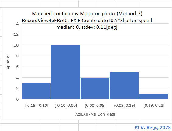
convergence_angle=-4.21667°
After doing a few iterations the best convergence_angle
was -4.21667°.
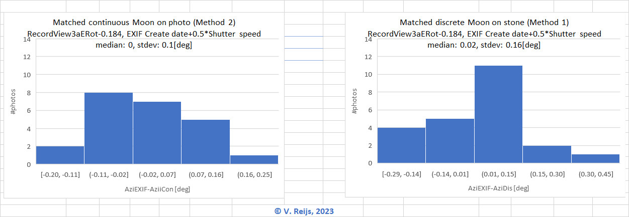
This gives an median RotVertCon of
around 0deg (with a standard deviation of 0.1deg) for Method 2. As
expected, the standard deviation has not changed much compared to
other convergence_angle.
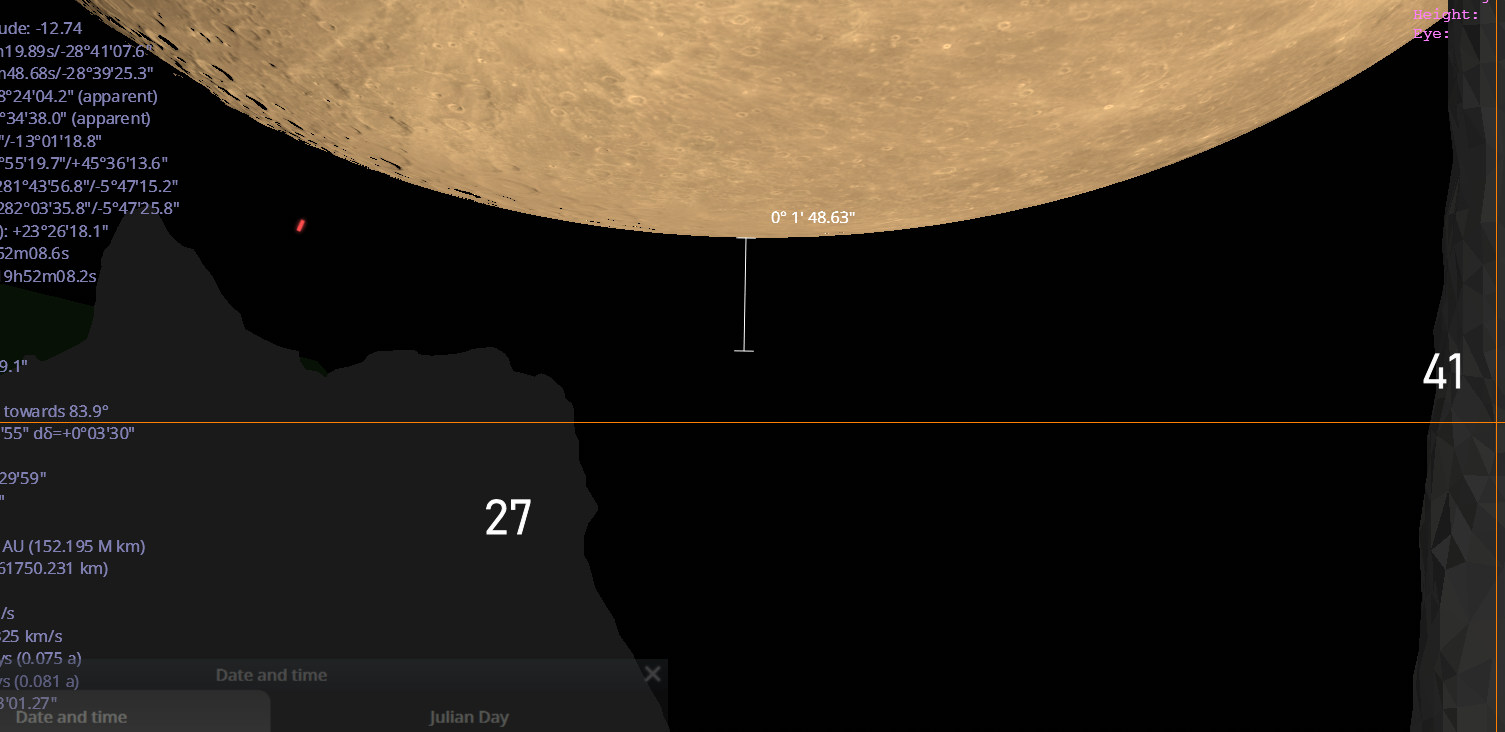
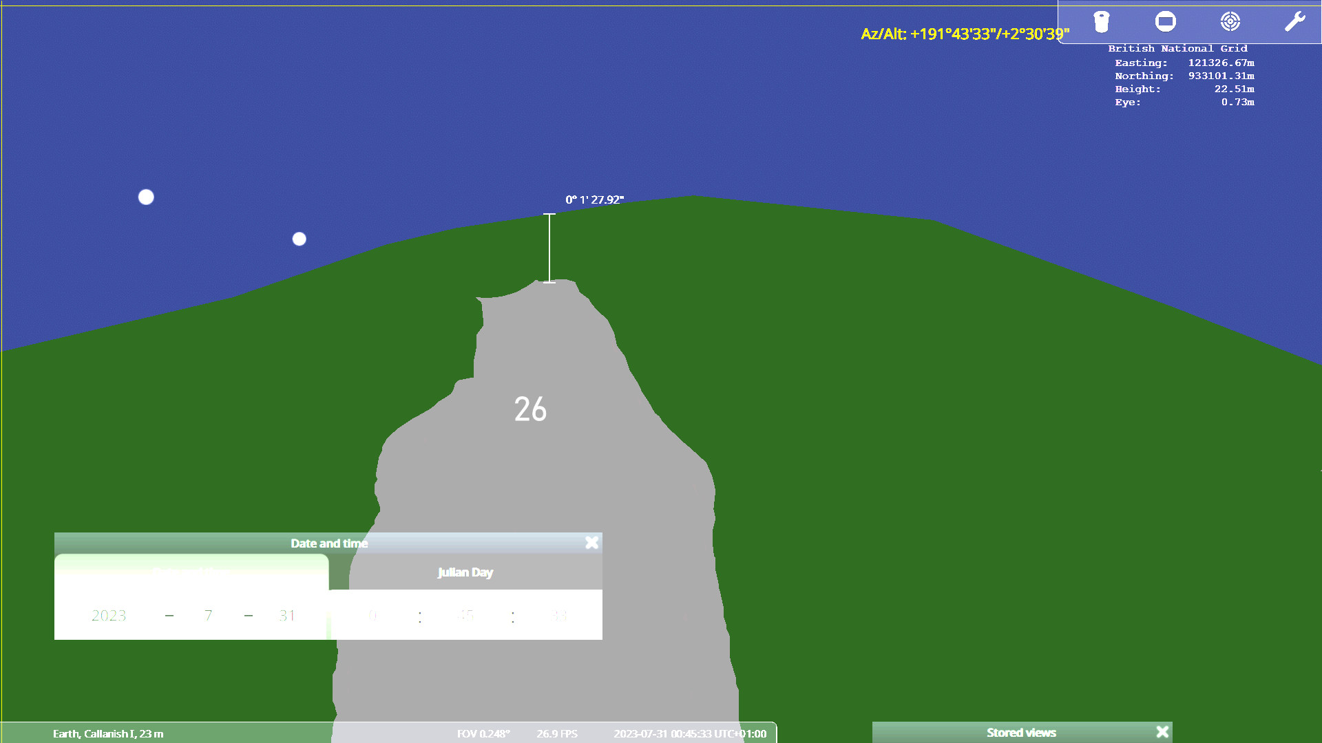
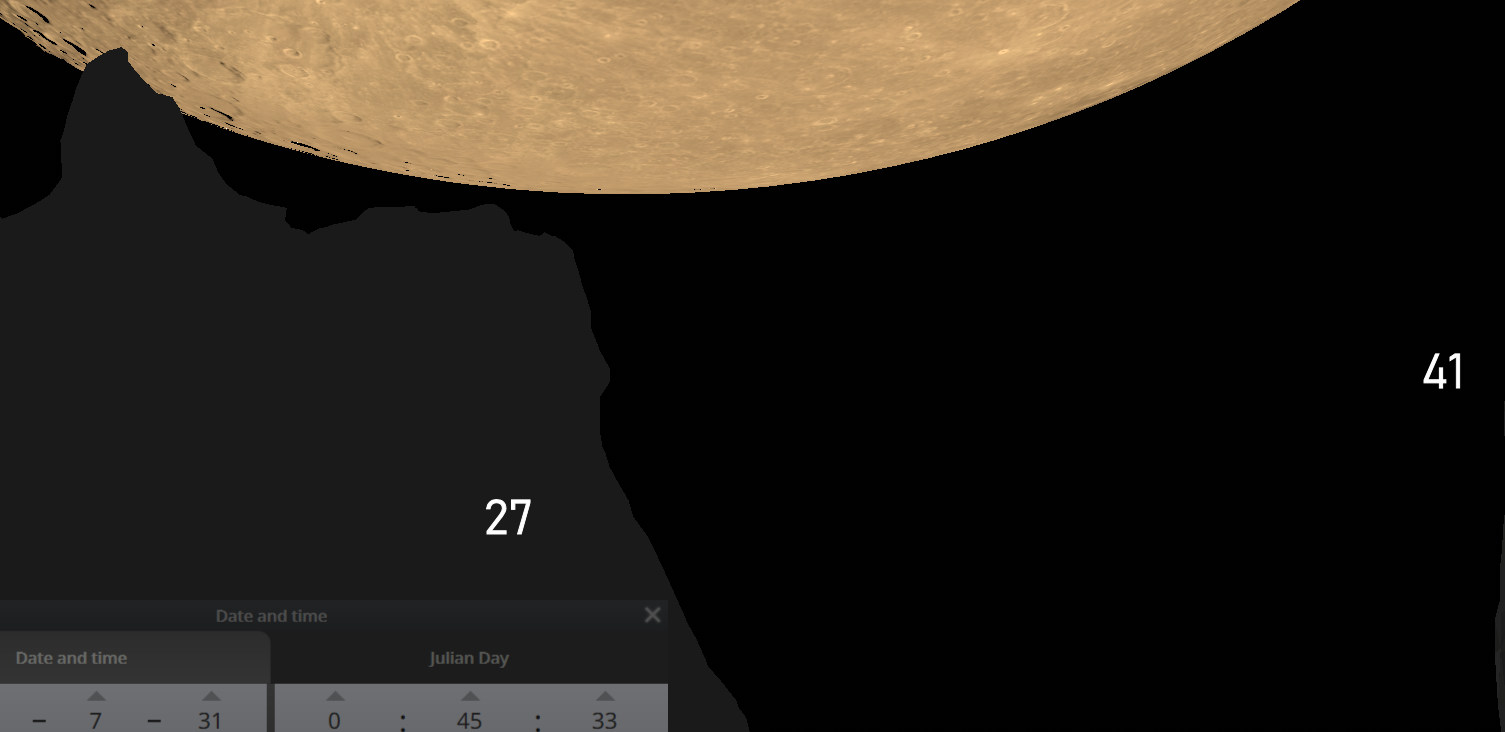
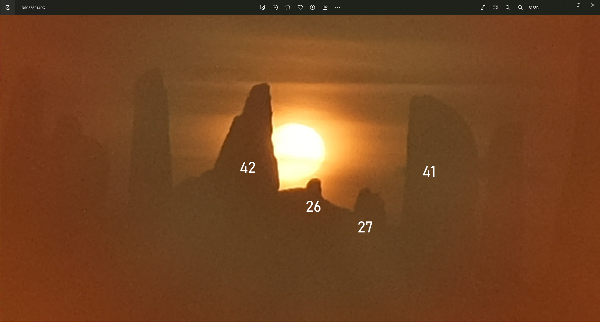
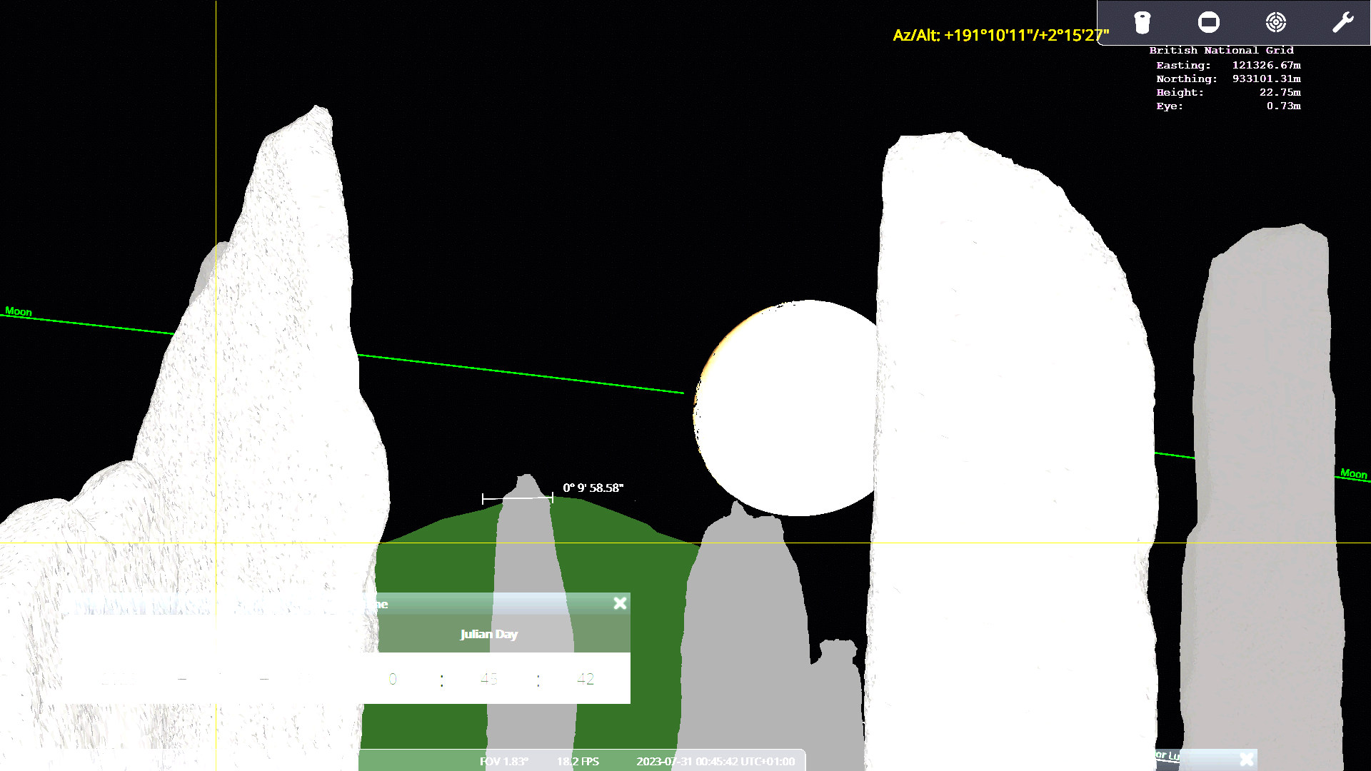
Apparent altitude
The Moon is visible on photo DSCF8622 where it just touches stone
27. In Stellarium (using convergence_angle=-4.21667°) the
Moon is lower; thus we need to rotate the East-West axis (RotEW)
of the 3D laser scan with some 7.1'.
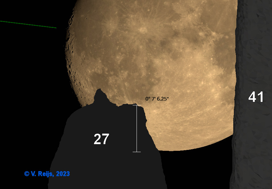
Remark:
The peak seen on stone 27 looks to be an artefact. Is being
investigated. Another possible artefact (missing, or wrong
normal, triangles) might be at the top of stone 32.
Positioning whole 3D laser scan (transform)
The whole 3D laser scan needs to be lowered compared to Cnoc an
Turso, equivalent to 8.5' (Cnoc-Vertangle) over a distance of
DistanceCnoc (around 175m).
This amounts to a lowering of the whole 3D laser scan of some 44cm (Transvert).
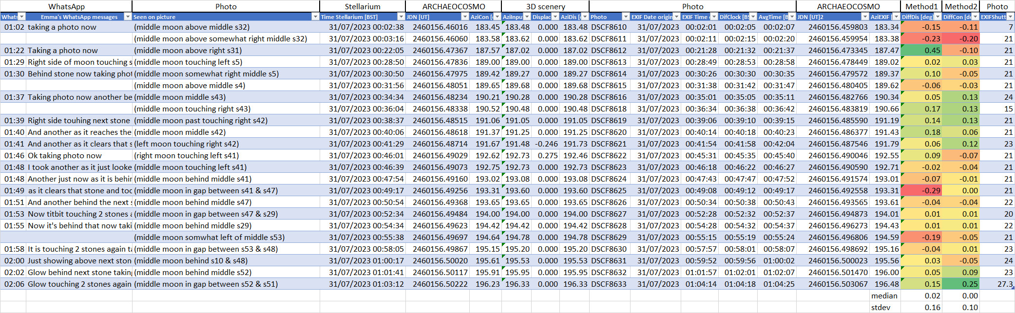
Derived data from photos
Here is the azimuth related information (convergence_angle
= -4.21667°) from the taken photos (click below picture to
see it larger):
Findings first iteration
Initial adjustments (at the point of stone 8) for the Calanais I 3D laser scan (and
keeping the Cnoc an Turso DSM the same) are:
- Aligning azimuth (RotVertCon): a
vertical axis rotation of some -0.184deg (due to lacking
georeferencing of Calanais I).
Its standard deviation is relatively large (0.1deg, equivalent
to 30sec), and this is due to the Method's inaccuracy of visual
inspecting the photos. Observations with binoculars and
stopwatch might produce more precise values.
- Aligning altitude (RotEW): an East-West axis
rotation of some -0.118deg (due to lacking georeferencing of
Calanais I).
- Aligning with Cnoc an Turso (Transvert):
a vertical transform of some -44cm (due to lacking
georeferencing of Calanais I and DSM resolution of Cnoc an Turso). This
value does looks too large.
In general, this transformation might not be fully correct
(certainly for positions closer to Cnoc an Turso).
These three adjustments might need an iterative process (as
things might be depending on each other). The resultant scenery
is: callanish1_Readjusted20230817.
Second iteration
The first iteration
(based on callanish1_Readjusted_20230505) did not provide
the correct azimuth, apparent altitude and height of whole 3D
laser scan. The following sections provide the results of version
callanish1_Readjusted20230817.
Hopefully this second iteration gives for all three adjustment a
value of (close to) zero.
Azimuth
RotVertCon = +0deg
Apparent altitude
RotEW = +0.03deg
This unexpected difference could be related to the fact that an
up-down rotation (azimuth) of 0.26deg (in first iteration) will also
change the apparent altitude (around 0.029deg). This 0.029deg is
close enough to the above
0.03deg.
Positioning whole 3D laser scan
Transvert = +31cm, but transform
adjustments will be postponed to following iteration, as there
exist some uncertainty of the method:
Transvert = +0cm
TransEW = +0cm
TransNS = +0cm
Third iteration
The second iteration
(based on callanish1_Readjusted20230817) did not provide
the correct apparent altitude. The following sections provide the
results of version callanish1_Readjusted20230818.
Azimuth
RotVertCon = +0deg
Apparent altitude
RotEW = +0deg
The above match is good enough, we need to remember that stone 27
also has an artefact
(the 3D laser scan does not fully match the photo), which needs to
be solved first.
Positioning whole 3D laser scan
Visually no change from the
3D scenery callanish1_Readjusted20230817, This is also
expected as there was no adjustment made.
We need to compare this with the photo:
A new model has been made to determine, which
only gives a slight difference from the first model. This results in an average
vertical transform of:
Transvert = +24cm
TransEW = +0cm
TransNS = +0cm
Fourth iteration
The third iteration
(based on callanish1_Readjusted20230818) did not provide
the correct apparent altitude of Cnoc an Turso. The following
sections provide the results of version callanish1_Readjusted20230818-2.
Azimuth
RotVertCon = +0deg
Apparent altitude
RotEW= +0deg
Positioning whole 3D laser scan
Transvert = +0cm (for now this is
ok-ish).
This 10' could be a transform into the East-West direction of:
TransEW = -50cm at the end this was
changed to TransEW = -30cm
TransNS = +0cm
Fifth iteration
The fourth iteration
(based on callanish1_Readjusted20230818-2) did not provide
the correct east-west transform of Cnoc an Turso. The following
sections provide the results of version callanish1_Readjusted20230818-3.
Azimuth
RotVertCon = +0deg
Apparent altitude
RotEW = +0deg
Positioning whole 3D laser scan
Transvert = +13cm
An extra 4' could be a transform into the West direction of TransEW
= -20cm, but this will mesh up the rest of Cnoc an Turso's
skyline. So no TransEW = +0cm
Instead of this a TransNS = +18cm
will be performed.
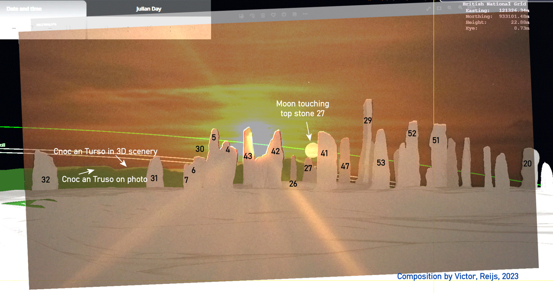
Summary of results of fifth iteration
Here is the overall resulting overview of fifth iteration (right
clicking the picture enlarges it):

Some findings of an overlay of
Stellarium screen grab (light green/white/black) with photo
(DSCF8618.jpg: slightly rotated, orangy, yellow, darker green, brown
borders):
- there sometimes are thin brown borders (smaller than 1arcmin)
on the right sides of stones (e.g. stone 42 and 29). So there is
not a 100% match between the 3D scenery and the photo. This is
thus within an accuracy of around 1 arcmin.
- Nearby stones (e.g. 7, 6, 5, 4) are just as well positioned in
the 3D scenery (compared to photo) as more far away stones (e.g.
32, 43, 41, 29).
- The Moon's azimuth is on average ok (sample of 23 photos), but it has a large
standard deviation of around 6arcmin. So RotVertCon
is ok, but its standard deviation not. This is too large; see conclusions for some
remedies.
- The Moon touches top of stone 27 nicely (within 1 or 2 arcmin)
in the 3D scenery. So RotEW is ok.
- The overall Cnoc an Turso's skyline (light green) in 3D
scenery is still some 3arcmin too high compared to the photo's
(darker green). A Transvert = 13cm (3D
laser scan higher up) would possibly be needed.
- Cnoc an Turso's peak near stone 26 is in the 3D scenery some
4arcmin too much to the West compared to the photo. The rest of
both Cnoc an Turso's skylines peaks and dips look to match
ok-ish. This could be due to the 25cm resolution of the Cnoc an
Turso's DSM, so no additional TransEW.
Sixth iteration
The fifth iteration
(based on callanish1_Readjusted20230818-3) did not provide
the correct vertical and east-west transform of Cnoc an Turso. The
following sections provide the results of version callanish1_Readjusted20230818-4.
Azimuth
RotVertCon = +0deg
Apparent altitude
RotEW = +0deg
Positioning whole 3D laser scan
Transvert = +0cm
TransEW = +0cm
TransNS = -18cm (this amount would
result in an 0.5arcmin reducing the seen width of far away
stones).
Some findings:
- There are larger brown borders around stones than in the fifth
iteration, so less good matching. Could this be due to the
TransNS?
- IMHO there is not enough information to base TransNS
on.
- Cnoc an Turso's skyline has overall the right apparent
altitude (comparing green with light green), so Transvert
is now correct
- Cnoc an Turso's peak near stone 26 (light green) could still
be somewhat more to the left in the 3D scenery. But we
leave this, as it will mesh up the rest of Cnoc an Turso's
skyline (possibly due to 25cm resolution of Cnoc an Turso's
DSM).
Seventh iteration
The sixth
iteration (based on callanish1_Readjusted20230818-4)
did not provide the correct vertical and east-west transform of
Cnoc an Turso. The following sections provide the results of
version callanish1_Readjusted20230821.
Azimuth
RotVertCon = +0deg
Apparent altitude
RotEW = +0deg
Positioning whole 3D laser scan
Transvert = +0cm
TransEW = +0cm
TransNS = +0cm
Overview of iterations
|
Iterations from initial 3D scenery
|
1st*
|
2nd
|
3rd
|
4th
|
5th
|
6th
|
7th
|
230505
|
230817 |
230818 |
230818-2 |
230818-3 |
230818-4 |
230821
|
Start
|
RotVert
[deg] |
0
|
-0.184
|
-0.184 |
-0.184 |
-0.184 |
-0.184 |
-0.184 |
RotEW
[deg] |
0
|
-0.118
|
-0.088
|
-0.088 |
-0.088 |
-0.088 |
-0.088 |
TransEW
[cm] |
0
|
0
|
0
|
0
|
-30 |
-30 |
-30 |
Transvert
[cm] |
0
|
-44
|
-44 |
-20
|
-20 |
-7
|
-7 |
TransNS
[cm] |
0
|
0
|
0
|
0
|
0 |
+18
|
0
|
| Proposed |
RotVert
[deg] |
-0.184
|
+0
|
+0
|
+0
|
+0 |
+0 |
+0
|
RotEW
[deg] |
-0.118
|
+0.03
|
+0
|
+0
|
+0 |
+0 |
+0 |
TransEW
[cm] |
+0
|
+0
|
+0
|
-30
|
+0
|
+0 |
+0 |
Transvert
[cm] |
-44
|
+0
|
+24
|
+0
|
+13
|
+0 |
+0 |
TransNS
[cm] |
+0
|
+0 |
+0 |
+0 |
+18
|
-18
|
+0 |
The initial 3D scenery is callanish1_Readjusted_20230505.
Experiences
Overall accuracy
We have been able to position the 3D laser scan properly within
the 3D scenery. The accuracy is around 1 or 2 arcmins (the Moon's
azimuth looks to have somewhat lager standard deviation: 6arcmin.
this is due to
inaccurate timing).
Sequencing of adjustments
The best sequence of adjustments, by reducing interdependencies,
of rotations and transforms is:
- 3D laser scan RotVert
- 3D laser scan RotEW
- Cnoc an Turso DSM TransEW
- Cnoc an Turso DSM Transvert
Reducing the standard deviation of
Moon's azimuth due to timing
The Moon on the July 30
th/31
st photos was
somewhat overexposed; large exposure time (around 20sec); and
there were cloudy skies; and thus blurry contours of the Moon,
which caused the eperienced (large) standard deviation of ~0.1deg.
A few methods could help us here:
- An exposure time of less than 1 sec would give more crisp
touch, vanish, reappear and release moments of stone and Moon
(less movement blur of Moon); exposure time must be such that
the Moon's contour is just visible against stone contours.
Zoom-in in such a way that there are some 10 stones visisble
(FOV~10deg). Clear skies also make crisp photots, but we don't
have that in hand. Use binoculars to determine the
touch/vanish/reappear/release moments.
- A video (with timestamp in picture), this would be some 60
minutes of continuous video (not over-exposed for the Moon).
- Using binoculars (as a kind of theodolite) and a stopwatch (on
a sync-ed phone); will make sure one gets the touch and release
moments of stone and Moon more accurately.
- Other?
Method 1 will be utilised in the next Moon path.
Determining remaining rotation and transform
Of course there are still a transform (Cnoc an Turso's DSM in
North-South direction:
TransNS) and
rotation (3D laser scan around North-South axis:
RotNS)
possible; these are not yet investigated as these can't really be
determined using the camera location at stone 8. One would need a
camera location at stone 33 or 23 (and times of resp. set or rise
events of a celestial object).
A realistic
TransNS can't really be
determined (as the effect of this is marignal on celestial
directions).
The rotation
RotNS will not have effect on the
Cnoc an Turso's DSM, more on the positioning of 3D laser scan with
the celestial object.
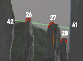
Artefacts in the 3D laser scan
A few stones in the 3D laser scan have some triangulation
artefacts (these were found as they were handy for aligning the
celestial object: red areas); stone 32 (error some 2arcmin: due to
possibly wrong normal of some triangles); stone 26 (error some 2
to 3arcmin: missing left side top and small bit on the right side
top); stone 27 (error some 2 to 3arcmin: missing left side top);
and stone 28 (has a mushroomed top).
These errors make up a part the accuracy of the whole 3D scenery
(expected to be around 1 arcmin), so they are not that serious
except if these missing stone contours are used for defining
'touching' moments. Upto now no stone contour that were missing,
were used.
Position of stone 33A (resolved)
A check needs to be done about the position of stone 33A in the 3D
laser scan (by making a photo of the east row of stones: 33A to
30). The position of that stone does not map the skyline made by
Ponting (1981, Fig. 2.10) and looks not to match sometimes between
the 3D scenery and a skyline photo. A photo check (DSCF8791, FOV
53deg and stones 33A to 30 in the middle of photo) has been done
and the locations of stones 33A to 30 are mapping the 3D
scenery's.
Replace skyline in direction of View B (resolved)
A SRTM 1" based skyline is not accurate enough in the
direction
of View B. A DSM for that skyline has been included
with
good results. Permission has been gotten (Oct. 2nd, 2023)
from
bluesky to utilised
this DSM.
Acknowledgments
I would like to thank the following people for their help and
constructive feedback: Emma Rennie, Georg Zotty and all other
unmentioned people. Any remaining errors in methodology or results
are my responsibility of course!!! If you want to provide
constructive feedback, let me know.
Disclaimer and Copyright
HomeUpSearchMail
Major content related changes: July 31, 2023