Simuleren van wind bij Nägeli artikel
Simuleren van wind
bij Nägeli artikel by Victor Reijs
is licensed under CC BY-NC-SA 4.0


Introductie
Als voorbeeld is op deze web pagina een simulatie voor een
windscherm (volgens artikel van Nägeli, 1953)
Er zijn nog wat andere voorbeelden: De Hoop (Den Oever), Makkinga's
Mölle
(voorheen Den Oord, Ommen), De Zwiepse Molen (Zwiep) en Impington Mill
(Impington).
Deze webpagina heeft de volgende paragrafen:
Sorry for the two langauges gebruikt in deze webpagina!
Vette paarse tekst heeft nog extra
aandacht nodig.
Informatie over de omgeving
- The ABL wind speed is 9.03m/sec@10m (which gives 5m/sec at
2.2m) and z0m of 0.03m. z0m
is determined from the table on page 222 of Nägeli [1953].
Remark: z0m =0.01 is determined from the table on
page 222 of Nägeli [1953]. This though does not provide a
significant change.
- CFD wordt gedaan voor wind uit Zuid (180deg).
- In all graphs the magnitude of the wind speed is provided.
Eigenschappen van obstakel
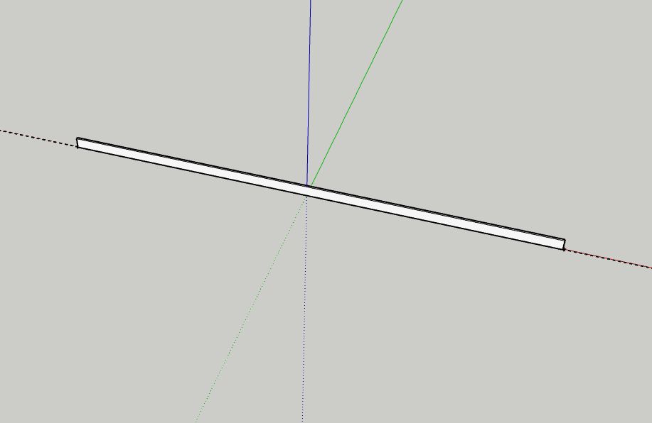
- One box (fence) of 25m (Nägeli's fence) long, 40cm thick ad
2.2m heigh
- Nägeli fence, has an optical porosity of around 15-20% and
45-55% [Nägeli, 1953, Bild 2].
- 3D model of Nägeli's fence in SketchUp:
- Include at the back (100m from fence) a small (dummy) box
(which is needed for being able to simulate things in CFD)
- Sluit af als klaar: 'Save' en 'Download' -> 'STL'
- Effort: 0.5 hours.
Editing 3D-model in SIMSCALE
We are making use of SIMSCALE. Make sure
you make a Community Plan
account. This Community Plan allows only for 10 simulations (but
one can do many more; but with more manual work). Anyway make
sure you have a good CAD-model and that you train/educate yourself around SIMSCALE.
The following steps can be done:
- Het simulatie project staat hier.
- Import het STL
model
- Edit this (not yet rotated) model by: Edit a copy
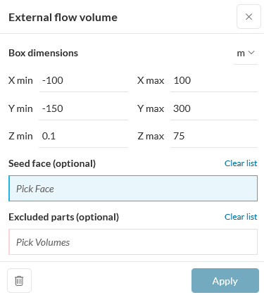
- Make a Flow Volume -> External waarbij de
poreuze objecten (bomen: 'Excluded parts') niet deelnemen aan
het 'External flow volume'.
Zie voor richtlijnen mbt vrije afstanden rondom het model hier [Franke,
2007]:
- Xmin, Xmax: minimaal 5*hoogte/grootte hoogste
obstakel [Franke, 2007, page 17] extra aan linker en rechter
kant van 3D-model. In dit geval ~5*~2.2m (fence): ~ 10m
- Ymin: Distance in front of model (in Y-direction)
minimaal 8*hoogte/grootte hoogste obstakel [Franke, 2007,
page 18] extra aan voorkant van 3D-model. In dit geval
~8*~2.2m (fence): ~ 20m
- Ymax: Distance at back of model (in Y-direction)
minimaal 15*hoogte/grootte hoogste obstakel [Franke, 2007,
page 18] extra aan achterkant van 3D-model. In dit geval
~15*~2.2m (fence): ~ 40m
- Zmin: Ground (in Z-direction) minimaal om invloed
van modelerings afrondingen te voorkomen: ~ 0.1m
- Zmax: Height (in Z-direction) minimaal
6*hoogte/grootte hoogste obstakel [Franke, 2007, page 17].
In dit geval ~6*~2.2m (fence): ~ 15m
- By the way, the default values in SIMSCALE were always
somewhat larger than the above, so its defaults are also ok.
Except for Zmin; I would put that always at 0.1m.
- In this simulation a much larger area around the fence
model has been taken.
- Delete the dummy box, maar niet de fence
- Save
- Effort: 0.5 hours.
Configureren van de CFD
Take the following steps (if not default, it is explicitly
mentioned in below steps):
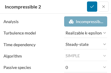
- Goto SIMULATIONS +
- Incompressible -> Turbulence-model -> Realizable
k-epsilon [Franke, 2007, page 14]
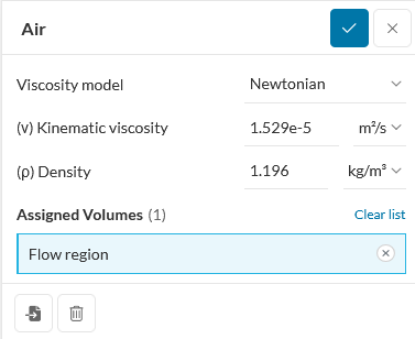
- Materials -> Air -> Apply
Assigned Volumes -> Flow region
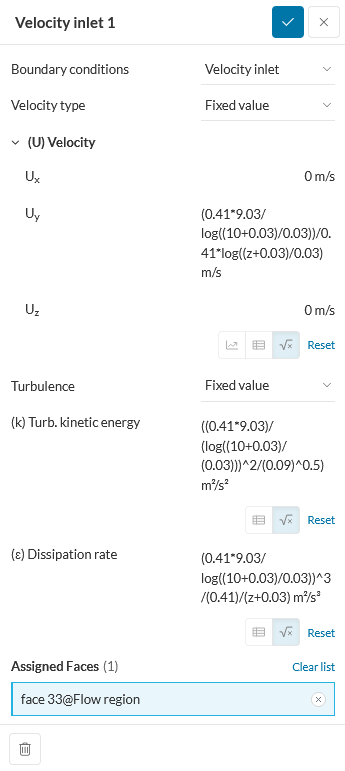
- Boundary conditions
- Velocity Inlet
Assigned Faces -> the wind side
(U) Velocity -> Uy -> ABL Formula
(6.4m/sec at 10m and z0m=0.01m, the wind direction
is 180deg [S])
(0.41*9.03/log((10+0.03)/0.03))/0.41*log((z+0.03)/0.03)
Turbulence -> Fixed value
(k) Turb. kinetic energy -> ABL derived Formula
(((0.41*9.03)/(log((10+0.03)/(0.03)))^2/(0.09)^0.5)
(ε) Dissipation rate -> ABL derived Formula
(0.41*9.03/log((10+0.03)/0.03))^3/(0.41)/(z+0.03)
Save
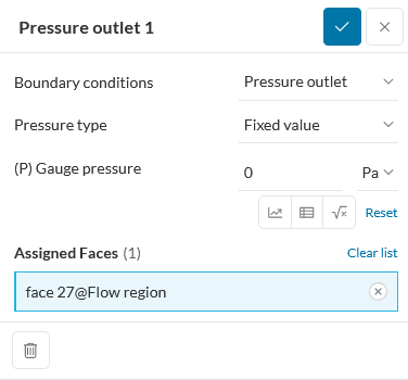
- Pressure outlet
Assigned Faces -> opposite inlet side
Save
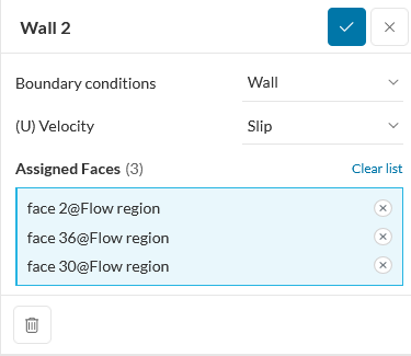
- Wall
Assigned Faces -> two sides and top
(U) Velocity -> Slip
Save
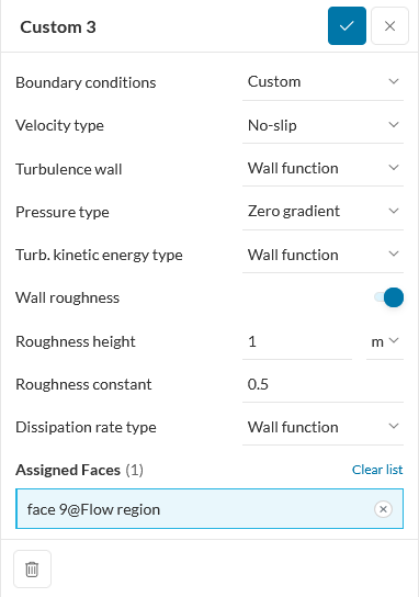
- Custom (ground)
Assigned Faces -> bottom side
Wall roughness -> On
Roughness height -> 1m
Roughness constant -> 0.5
Save
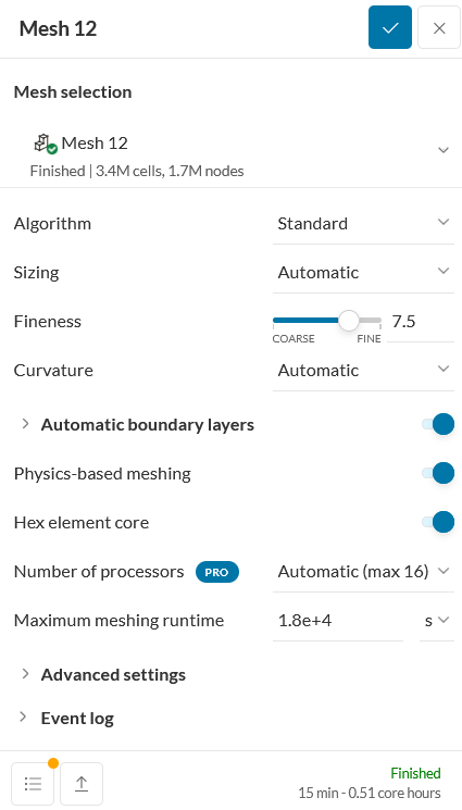
- Mesh
25m fence: Fineness = 7.5 (1.5Mcells)
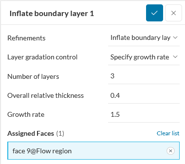
- Mesh -> Refinements -> Inflate boundary layer
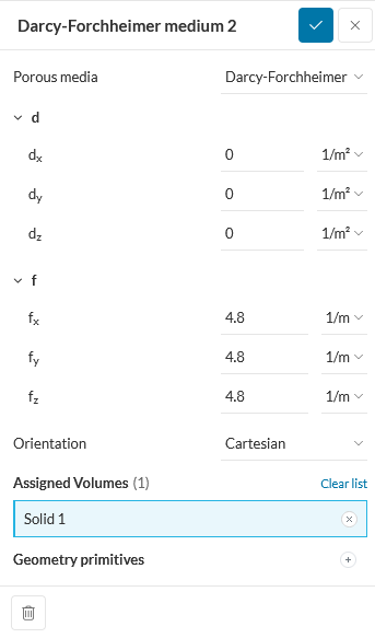
- Advanced concepts -> Porous media ->
Darcy-Forchheimer Medium
Forchheimer coefficent f=12.8 (Dichte Wand) or
Forchheimer coefficent f=4.8 (Lockere Wand).
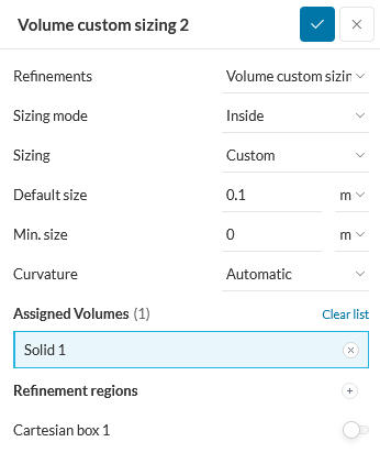
- Mesh -> Volume custom sizing
At least 4 cells in the thickness of 40cm
- Effort: 2 hours (excluding the time needed to evaluate the Direction
in perforated plate).
Uitvoering van de CFD
- Simulation Runs +
- Varying the mesh size:
Fineness
|
Size [Mcells]
|
Mesh [CPUh]
|
Run [CPUh]
|
5
default
|
0.5
|
0.8
|
0.8
|
7.5
|
1.5
|
0.3
|
4.0
|
9.2
|
10.5
|
1.8
|
26
|
Fineness of 7.5 has been used in below analysis.
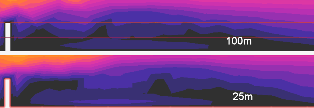
- Using a 100m long henge instead of a
25m henge, shows that the wind speed increases slower for a 100m
henge than for a 25m henge. So the shorter the obstacle the
faster the speed increase (at large distances).
- The Forchheimer coefficent f of the
modelled fence was tried to be matched with Nägeli's fence at
17.5% (Dichte Wand) The black curves (17.5% optical
porosity 25m fence) are from Nägeli [Bild 4, 1953] and the
colored curves (z0m=0.03m, f=12.8, 25m fence, Fineness=7.5)
are computed from CFD:
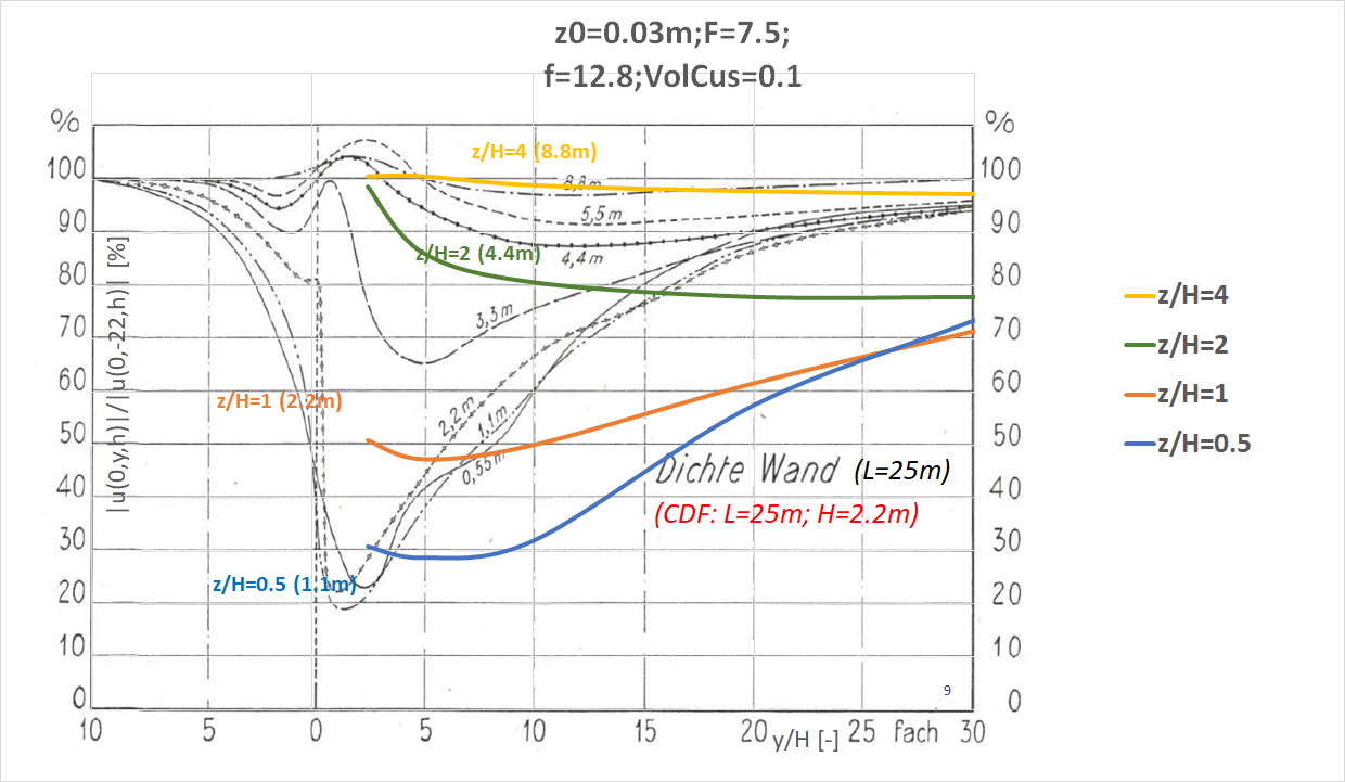
There is quite some difference between Nägeli and CFD.
- The Forchheimer coefficent f of the modelled fence was tried
to be matched with Nägeli's fence at 50% (Lochere Wand).
The black curves (50% optical porosity, 25m fence) are from
Nägeli [Bild 4, 1953] and the colored curves (z0m=0.03m,
f=4.8, 25m fence, Fineness=7.5) are computed from CFD:
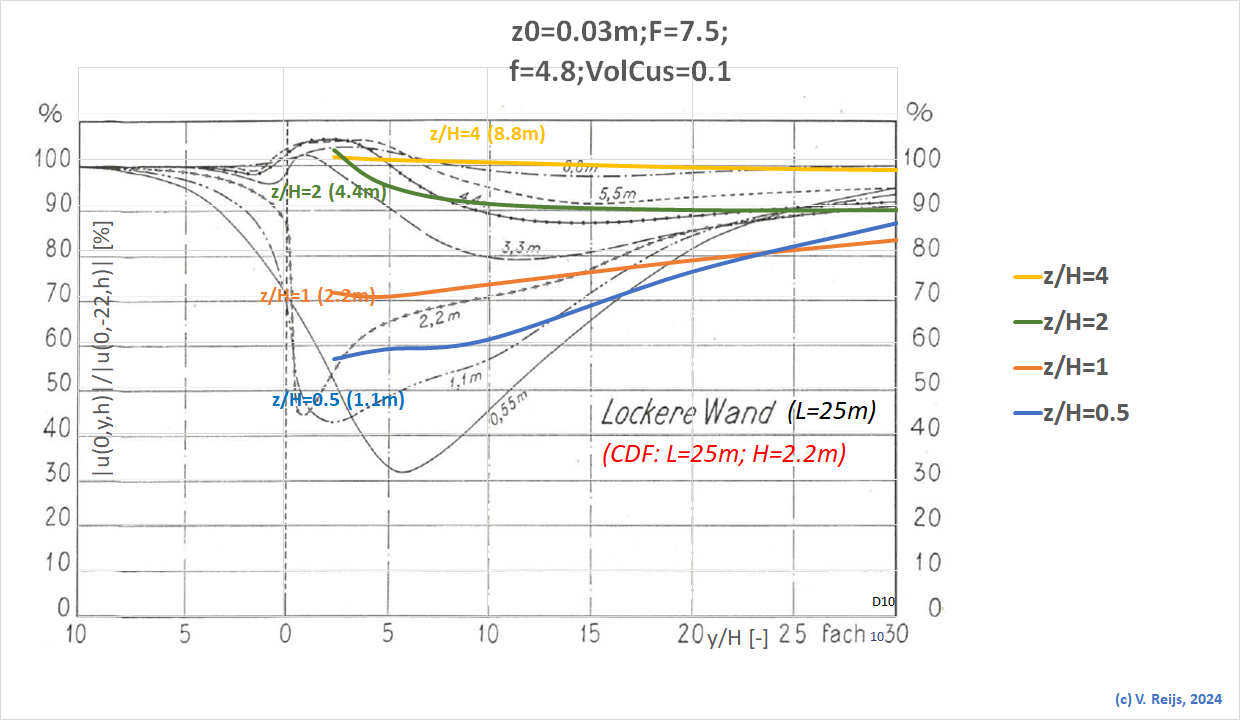
There is good mapping between Nägeli and CFD.
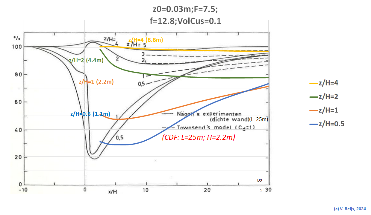
- The dip seen in the curves happens
nearer to he end of the obstacle if it is less porous (compare
above black&white curves of Nägeli).
- Beljaars [1979, page 42] compared this
with Townsend's model (by changing its Cd [to 1] for
best matching)::
- Effort: 4 hours.
Conclusions
- Most default values of SIMSCALE look ok, except:
- Use Realizable k-epsilon
- Zmin should be always 0.1m
- The higher the Fineness the better, somewhere
between 7.5 and 9 (instead of default of 5), or better: use
your own mesh configuration.
- Thoughs about the meshing:
- All mesh metrics stay within their defined min and max range;
at least for Fineness tested between 5 and 9.2 and
this 3D-model.
All rsiduals are smaller than 10-3.
- The Dichte Wand simulation does not match well. The Lochere
Wand is better simulated.
Remark: What causes this difference?
I thought perhaps it is difference between magnitude or
y-direction of wind speed, but these two don't have much
difference.
- An overview of outstanding issues/questions/etc is here.
- Now we would be able to look how Beljaars's method matches CFD. This
will be worked out here.
References
Beljaars, A.C.M.: Windbelemmering rond
windmolens. In: (1979).
Franke, Jörg et al. COST Action 732: Best
practice guideline for the CFD simulation of flows in the urban
environment. Brussels, COST Office 2007.
Nägeli, Werner, Untersuchungen
über die Windverhältnisse im Bereich von Schilfrohrwänden,
Mitt. Schweiz. Anst. Forstl. Versuchw., 29, 213–266,1953
Acknowledgements
I would like to thank people, such as
and others for their help, encouragement and/or constructive
feedback. Any remaining errors in methodology or results are my
responsibility of course!!! If you want to provide constructive
feedback, please let me
know.
Major content related
changes: October, 30, 2024